-40%
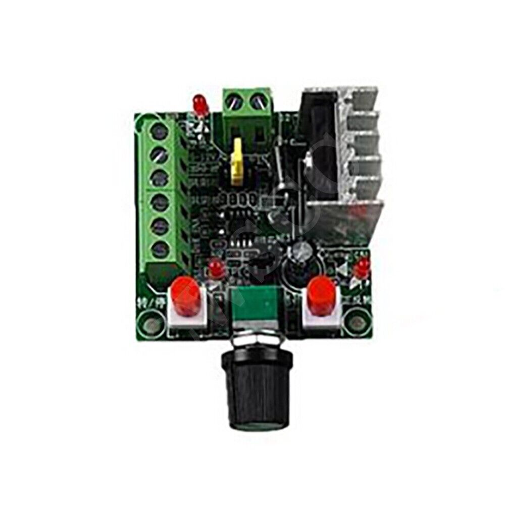
Simple controller for stepping motor drive Pulse generation PWM speed controller
$ 4.21
- Description
- Size Guide
Description
1. Product Description:1. When the controller generates a pulse frequency signal, it can be supplied to the stepper driver as a signal. If you want to control the stepper motor, it must also be equipped with a driver.
This simple controller + stepper driver + stepper motor + DC power supply can form a simple control platform.
2. The controller can generate pulse frequency signal and PWM pulse width signal. There is a jumper on the board, which can be set and selected. By default, it is set to generate pulse frequency signals.
REQ is to generate a pulse frequency signal
PWM is to generate PWM signal
3. When the controller generates a pulse frequency signal, there are three frequency signals of high, medium and low, which can be selected by the jumper. The frequency parameters are about:
High: 5.8KHZ-127KHZ
Middle: 590HZ-15.8KHZ
Low: 82HZ-2.3KHZ,
Frequency measurement: PUL and common cathode (GND) ports can be measured.
4. There are 2 groups of power input for power supply, and 2 groups only need to be connected to one group of power supplies. It is recommended to use a power supply above 15V. Connect to the power supply of the 2-position terminal, and do not reverse the positive and negative.
One group is the power supply connected to DC 15-160VDC, and the recommended working voltage is 15-80VDC.
The other group is 5-12VDC. When used with the driver, it is recommended to use a minimum of 12V, and do not use a 5V power supply for power supply. When 5V is not too much, the power supply is connected to "5-12V input", and the negative power supply is connected to "common cathode".
5. L*W*H: about 73*51*37MM
2. Wiring instructions
1. For the wiring of each wiring port, there are silkscreen instructions next to the terminals. Common cathode or common anode can be connected to the stepper motor driver.
PUL: Pulse port
DIR: Direction port
ENA: enable port
Common cathode: common ground (GND)
Common anode terminal: common terminal (+5V)
5-12V power supply is positive: the positive terminal of 12V power supply is generally empty, it is recommended to use a power supply above 15V.
For example: Common anode wiring with the driver, if it is the drive of 6 signal lines, the +5V common terminals of the 3 signals should be connected in parallel to form a line, all connected to the common anode terminal
Controller: Driver
PUL: pulse negative terminal (PUL-)
DIR: direction negative terminal (DIR-)
ENA: Enable negative terminal (EN-)
Common anode terminal: common terminal (COM or +5V or connect to the three ports of PUL+DIR+EN+ at the same time)
Note: if you want to use the start or stop function, the ENA enable terminal on the controller must be connected to the driver with a common cathode or a common anode
2. The forward and reverse rotation and start and stop of the motor can be controlled by pressing the buttons.
3. The speed of the motor can be controlled by adjusting the potentiometer to change the frequency.
4. The switch for forward and reverse rotation and start and stop of the original motor is an ordinary switch with self-locking.
